.webp) progamereviewh5.com
progamereviewh5.comDynamic Kinetic Sandbox Engineering: The Master Guide to Mechanical Construction, Energy Conservation, and Automation in Newton’s Playground

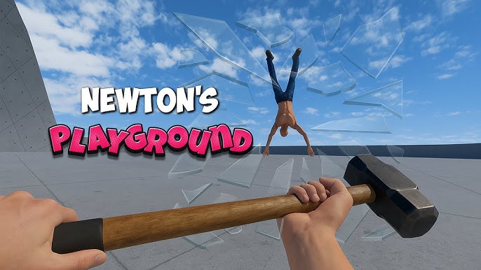
Newton’s Playground evolves the iconic physics-puzzle sandbox formula into a fully dynamic 3D engineering simulation. While the game retains its intuitive drag-and-drop heritage and accessible creative tools, it introduces expanded open-canvas environments, advanced material interaction matrices, deeper mechanical assembly systems, and comprehensive force vector analytics. Solving complex physics challenges or building elaborate continuous contraptions is no longer just about dropping a heavy sphere onto a basic ramp; it demands a systematic understanding of Newtonian mechanics, rotational torque, structural integrity, friction coefficients, and mechanical energy conservation.
Navigating these multi-layered physics canvases presents a steep learning curve. A single miscalculated lever arm ratio, an unmitigated vibrational harmonic, or an unchecked energy loss can instantly stall a forty-step mechanism, destroying hours of meticulous construction. Whether you are a solo kinetic artist or orchestrating a massive automated assembly with a co-op engineering crew, mastering Newton’s Playground requires transitioning from trial-and-error placement to proactive structural planning. This comprehensive guide provides step-by-step strategies to help you control mechanical forces, manipulate material friction, build high-efficiency mechanisms, and execute seamless automated chain reactions across every environment.
1. How to Master Environmental Calibration, Physics Solvers, and Base Frame Anchoring
The foundation of every successful kinetic contraption in Newton’s Playground is absolute structural stability and precise environmental setup. The simulation environment—encompassing global gravity vectors, air resistance, surface friction coefficients, and solver precision—governs the movement of every rigid body, cable, and spring. The Global Precision Meter measures how accurately the solver calculates micro-collisions and sub-frame joints. Leaving environmental variables uncalibrated or attaching load-bearing pivots to flexing frames introduces chaotic variance, eventually causing structural binding, joint snaps, or kinetic energy decay.
To eliminate unpredictable behavior while building complex contraptions, you must master the art of "frame anchoring." Before adding moving linkages, establish an immovable structural chassis pinned hard to the global grid using static substrate beams. Calibrate solver iteration sub-steps in the world settings to prevent high-velocity objects from clipping through tracks. Maintaining a rigid, low-vibration base frame keeps force calculations predictable, allowing your mechanisms to execute with sub-millisecond consistency across hundreds of test runs.
Core Environmental Management Rules
- Grid Alignment: Always snap primary pivot axles and load-bearing trusses to the global grid to prevent off-axis structural drift.
- Solver Precision: Increase physics solver sub-steps to high-fidelity mode when designing high-velocity impacts or small-scale gear linkages.
- Vibration Dampening: Mount heavy moving parts on rubber dampening blocks or cross-braced A-frame trusses to absorb unwanted structural oscillations.
2. How to Level Up Mechanical Efficiency, Calibrate Material Traits, and Balance Mass Distribution
A major innovation in Newton’s Playground is the deep Material Interaction and Mass Distribution Matrix. As you construct mechanisms, test force transfers, and analyze stress overlays, you unlock advanced material properties and mechanical tuning tools. These traits can be applied to core components—Planks, Spheres, Cables, and Gears—allowing you to tailor every structural element to match your specific mechanical requirements.
Adjusting Material Density and Restitution (bounciness) is mandatory for optimizing energy transfer. High-density tungsten components provide maximum momentum for driving heavy levers, while light carbon-fiber beams reduce rotational inertia in fast-operating escapements. Polishing contact surfaces lowers friction coefficients for high-speed transit rails, while increasing rubber elasticity creates spring-loaded actuators that store and release immense potential energy on demand.
Component Tuning Strategy
- Low-Friction Transit (Priority 1): Set rail material friction to 0.05 or lower and restitution to 0.00 to preserve linear momentum along extended transit tracks.
- Mass Distribution (Priority 2): Position heavy tungsten masses at the tips of primary levers to maximize kinetic impact force ($p = mv$) on receiving targets.
- Inertia Minimization (Priority 3): Use hollow aluminum or carbon-fiber materials for high-speed linkages to reduce rotational resistance ($I = mr^2$) and speed up trigger response times.
3. How to Dominate Kinetic Energy Conservation, Momentum Transfer, and Booster Systems
Generating, preserving, and transferring kinetic energy requires a steady understanding of mechanical conservation laws and gravity management. Moving payloads across long distances demands careful energy budgeting. Incorporating active momentum boosters—such as gravity drops, counter-weighted pendulums, and pre-loaded spring launchers—provides a reliable boost of kinetic energy, ensuring objects cross expansive canvases without stalling.
In addition to passive gravity ramps, constructing active "Booster Nodes" generates renewable momentum along extended runs. Booster nodes range from simple weighted rocker arms that drop fresh kinetic weights behind a rolling sphere, to complex flywheel accumulators that store rotational energy over time. High mechanical efficiency ratings lower energy decay across transit lines, ensuring that downstream triggers receive sufficient force to trip heavy latches or dislodge locked security pins.
4. How to Design, Assemble, and Optimize Complex Mechanical Toolkits
Mechanism assembly in Newton’s Playground expands upon classic physics construction, featuring dozens of customizable joints, axles, pulleys, and gear trains. Every object—from a simple wooden plank and steel axle to a hydraulic piston and tension cable—can be combined into an automated mechanical utility. Mastering the assembly matrix is mandatory for overcoming complex spatial obstacles like vertical cliffs, wide gaps, and heavy containment doors.
To build reliable mechanisms safely, you must construct balanced chassis frameworks and monitor real-time Stress Overlay Heatmaps. Using joints under loads that exceed their yield torque causes mechanical binding or structural failure; instead, reinforce stressed axles with secondary support bearings or distribute heavy loads across compound pulley systems. Always monitor joint wear and alignment during high-speed operations.
Essential Assembly Configurations
- Torque Multiplier: Asymmetric Lever (5:1 Ratio), Ball-Bearing Axle, Triangular Under-Truss. Primary Use: Amplifying light marble drops to lift heavy gates.
- Vertical Platform Elevator: Zero-Elasticity Cable, Dual Low-Friction Pulleys, 5:1 Counterweight Ratio. Primary Use: Moving heavy payloads vertically up multistory structures.
- Impact Absorber: Progressive Tension Spring, Rubber Friction Wedge, Dynamic Slider Rail. Primary Use: Stopping high-velocity spheres without destructive recoil.
- Escapement Release: Dual-Pawl Gear, Offset Balance Weight, Precision Trigger Latch. Primary Use: Regulating mechanical timing and releasing sub-routines.
5. How to Eliminate Energy Losses and Prevent Structural Vibrations
Allowing kinetic energy to bleed off into unwanted heat, surface friction, or structural wobble invites machine failure. Scheduled stress spikes occur when heavy masses strike static targets or high-speed gears jam. If kinetic energy decays below critical trigger thresholds, downstream mechanisms fail to trip, bringing the entire chain reaction to a halt.
Preventing mechanical failure requires building vibration-isolated sub-frames and low-friction transit corridors. You can install rubber isolation dampeners at main joint anchors, use dual-rail guide tracks to minimize rolling resistance, or set up one-way mechanical ratchets to lock levers after impact. Advanced builders create isolated sub-routines in separate structural bays where frame vibrations never transfer to sensitive trigger latches.
Structural Stability Checklist
- Dual-Rail Alignment: Replace flat ramps with two narrow parallel beams spaced at 60% of the sphere's diameter to eliminate lateral drift and drag.
- Ratchet Installation: Attach one-way mechanical ratchets behind primary pendulum axles to prevent double-strikes and back-recoil.
- Vibration Isolation: Insert high-friction rubber pads between load-bearing structural trusses and static background anchors to absorb frame flex.
6. How to Build Precision Pulleys, Cable Lifts, and Hydraulic Timing Loops
When horizontal space is limited or vertical height must be gained, going vertical or introducing controlled time delays provides an ideal solution. Vertical energy routing requires high-tension cable constraints, frictionless pulley guides, and precise mass balancing to prevent cable snap or elevator free-falls. Always cover vertical elevator shafts with catch baskets or guide rails to keep payloads aligned during transit.
Hydraulic and pneumatic fluid systems offer space-efficient timing control across multi-stage contraptions. Using fluid particle emitters and adjustable iris valves, you can create dripping fluid timers that fill tipping buckets at mathematically predictable rates. Fluid delay loops allow downstream platforms to reset, gates to swing open, or parallel sub-routines to synchronize before the main payload continues its transit path.
7. How to Construct Mechanical Logic Gates, Triggers, and Synchronization Nodes
Advanced contraptions in Newton’s Playground feature complex mechanical logic systems, including gravity-fed latches, balance-beam AND/OR gates, and pre-loaded NOT signal inverters. Tripping a logic gate without satisfying its input conditions results in a blocked path or an aborted launch. Bypassing these conditional checks requires building precise mechanical triggers and multi-input balancing nodes.
Constructing Pure Mechanical Logic Nodes
- AND Gate (Dual-Pin Bridge): Suspend a tipping bridge on two independent locking pins. Require two separate mechanical impacts from parallel sub-chains to pull both pins before the bridge can drop.
- OR Gate (Convergence Funnel): Build a sloped dual-lane track that feeds into a single shared trigger latch, allowing an input from either path to release the main payload.
- NOT Gate (Signal Inverter): Hold a compressed launch spring back using a weight-loaded rocker arm. If the incoming payload arrives, it keeps the spring locked; if absent, an offset weight releases the spring to trigger a backup routine.
8. How to Troubleshoot Mechanical Failure, Energy Decay, and Boundary Clipping
Moving past basic contraptions requires mastering environmental diagnostic tools. Once your machine spans multiple vertical tiers, energy dissipation, harmonic flex, and physics solver bugs present final engineering challenges to your grand finale.
Troubleshooting complex machines requires diagnostic overlay tools. Enabling the Velocity Heatmap Overlay highlights kinetic energy loss across tracks in real time, while the Stress Analysis View reveals load-bearing joints approaching structural failure. Designing reliable contraptions requires building safety margins into every handoff, ensuring that energy transfers retain a 20% power reserve above the minimum force required to trip downstream triggers.
System Recovery Protocol
- Identify Energy Bleed: Activate the Velocity Heatmap to locate track segments where object velocity drops rapidly from high (red) to low (blue).
- Reinforce Flexing Joints: Replace single-beam vertical supports with triangular trusses to eliminate frame wobble under load.
- Prevent Frame Clipping: Increase world solver precision to 120 sub-steps per frame if high-velocity objects pass through solid geometry.
9. How to Coordinate Multi-Tier Cascades in Co-Op Engineering
Newton’s Playground fully supports local split-screen co-op for two players and online multiplayer for up to four engineers. Working in a squad introduces powerful collaborative opportunities that are impossible in solo mode. Tasks like structural frame assembly, mechanism tuning, and timing calibration can be split among squad members, drastically reducing construction time.
Cooperative builds demand clear communication and structural role division. Assign one player as the "Frame Architect" to build rigid chassis bases and static anchors, while the "Mechanic" tunes gear ratios and lever pivots, and the "Systems Engineer" calibrates fluid delay loops and logic gates. Synchronization is critical during multi-tier cascade tests; if one team member's sub-routine stalls or misfires, the entire interconnected machine grands to a halt.
10. How to Master Complex Mechanical Sandbox Challenges Across Advanced Environments
Every physics canvas in Newton’s Playground features distinct environmental gimmicks, gravity variations, and spatial constraints. From low-gravity lunar test chambers to high-wind canyon gaps and underwater buoyancy basins, mastering the game requires adapting your engineering style to match the physical realities of each space.
Environment Adaptation Matrix
- Lunar Test Chambers (Low Gravity): Increase object mass values and utilize compressed spring launchers to compensate for reduced gravitational acceleration.
- Canyon Wind Gaps (Atmospheric Drag): Enclose transit tracks within aerodynamic structural tunnels or use heavy tungsten payloads to resist lateral wind drift.
- Sub-Aquatic Basins (Fluid Buoyancy): Utilize hollow watertight vessels for upward vertical lift and calibrate fluid drag coefficients to control descent speeds.
Conclusion: Achieving Total Mechanical Automation
Mastering Newton’s Playground is a test of patience, mathematical adaptability, structural resourcefulness, and precision engineering. The game transforms physics puzzles into satisfying systemic challenges where every variable—from surface friction and rotational inertia to gear ratios and material density—can be controlled to your advantage. There is no single "correct" way to complete a canvas; true success comes from studying physical laws, recognizing mechanical flaws, and executing a well-engineered design.